A physical, positive press
Press once for on, again for off. The illuminated symbols are button markings, not a screen.
L10U · SQUARE-BUTTON SMART SWITCH
LANBON versionGlossy black square buttons meet a precisely outlined surround. Choose Tech Grey or Gold, then match the physical 1–4-gang model to your project's lighting circuits.
L10U-HS1-T · EU · Tech Grey · 1-gang
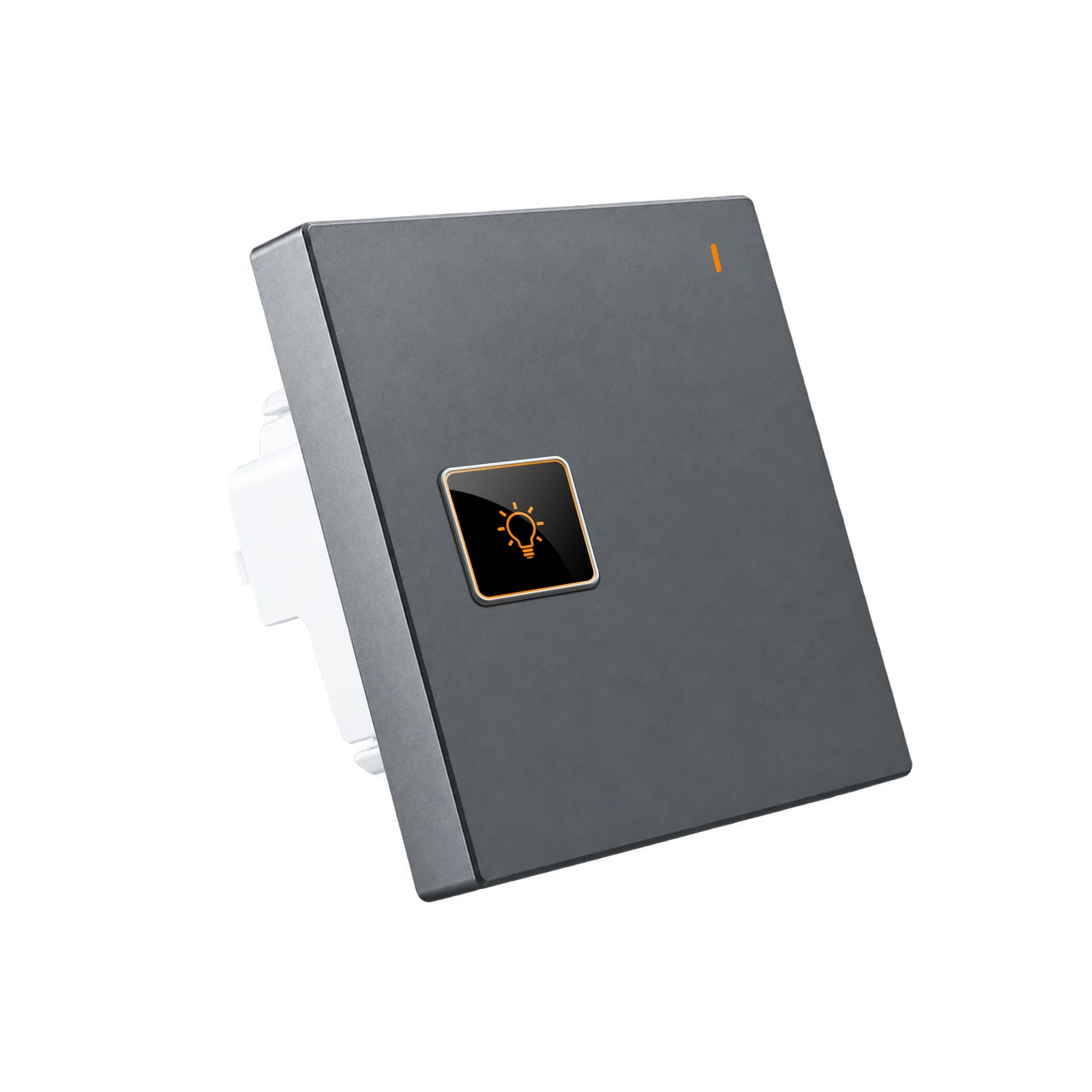
Press once for on, again for off. The illuminated symbols are button markings, not a screen.
Tech Grey and Gold share the same square-button identity across 1–4-gang options.
Discuss custom pictograms for project supply; text customisation is not supported.
BEFORE YOU SPECIFY
A qualified electrician must verify the wired circuits, lighting drivers and actual loads. This model switches lighting on/off; it does not dim lights or regulate fan speed.
AC 100–250V · 50/60Hz · Live and neutral required
L10U-HS1-T · 1-gang · Tech Grey
≤200 W per circuit, ≤200 W total. Never parallel outputs.
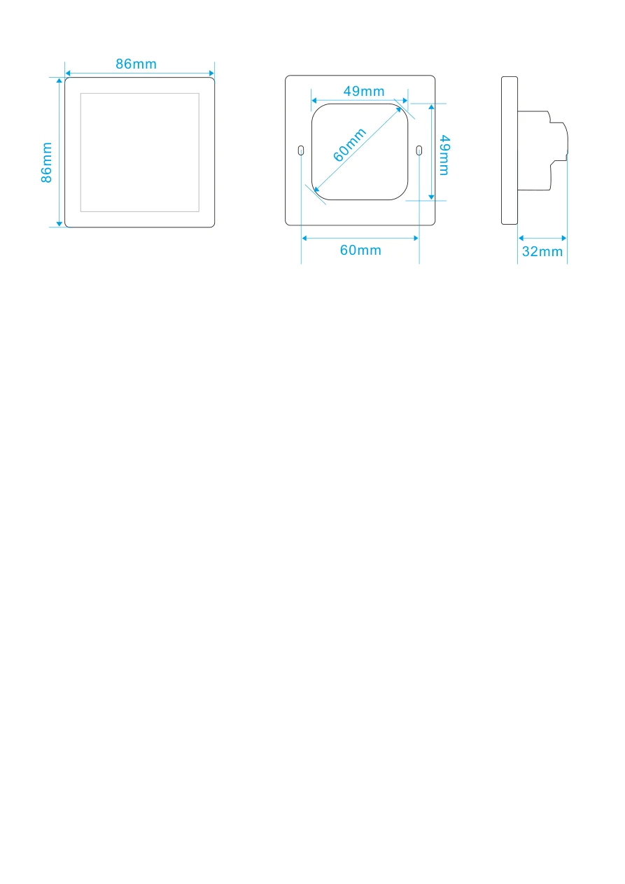
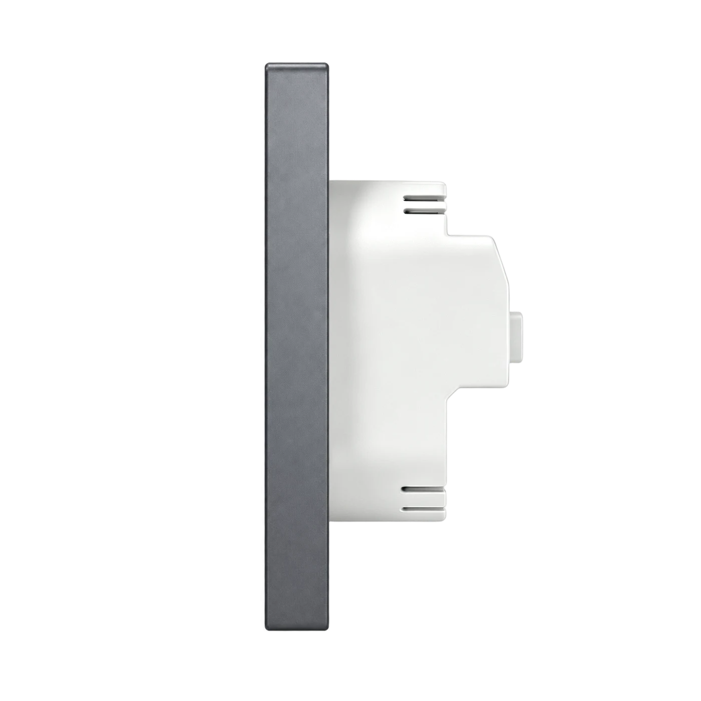
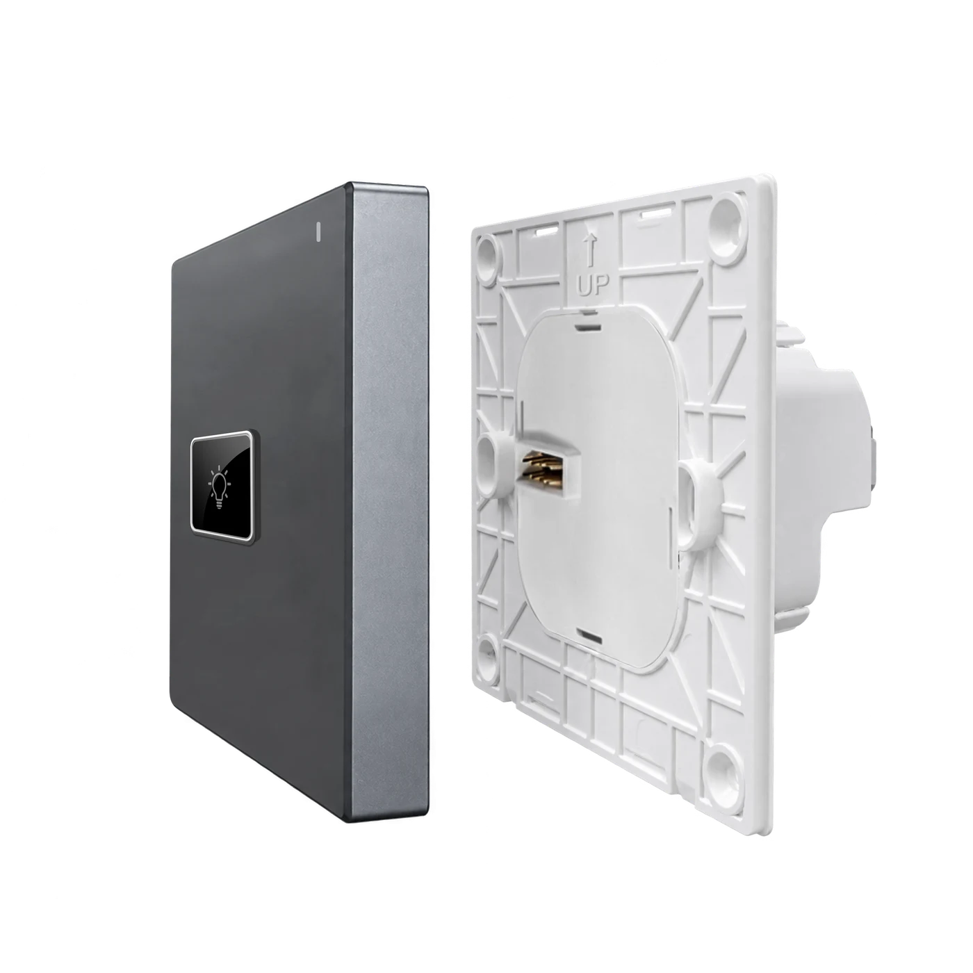
32 mm device body; the drawing specifies depth >38 mm. Verify usable space for conductors and terminals.
LANBON version uses the matching app and 2.4 GHz Wi-Fi setup. Remote services require internet.
FOUR PHYSICAL CIRCUIT COUNTS
Choose the physical 1-, 2-, 3- or 4-gang model for the wired circuits. The selected option is outlined below; change finish, format and circuit count in the common configuration band above.
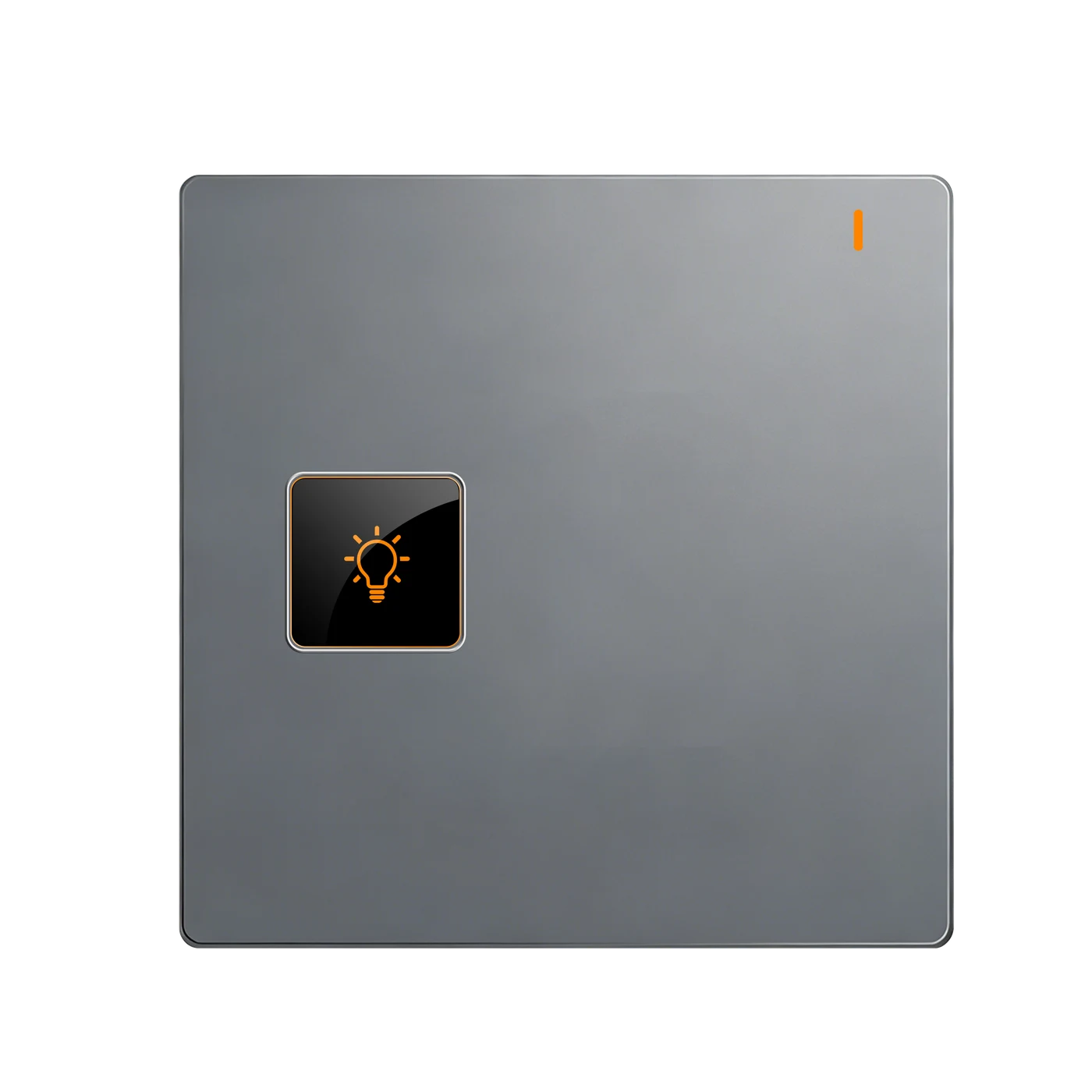
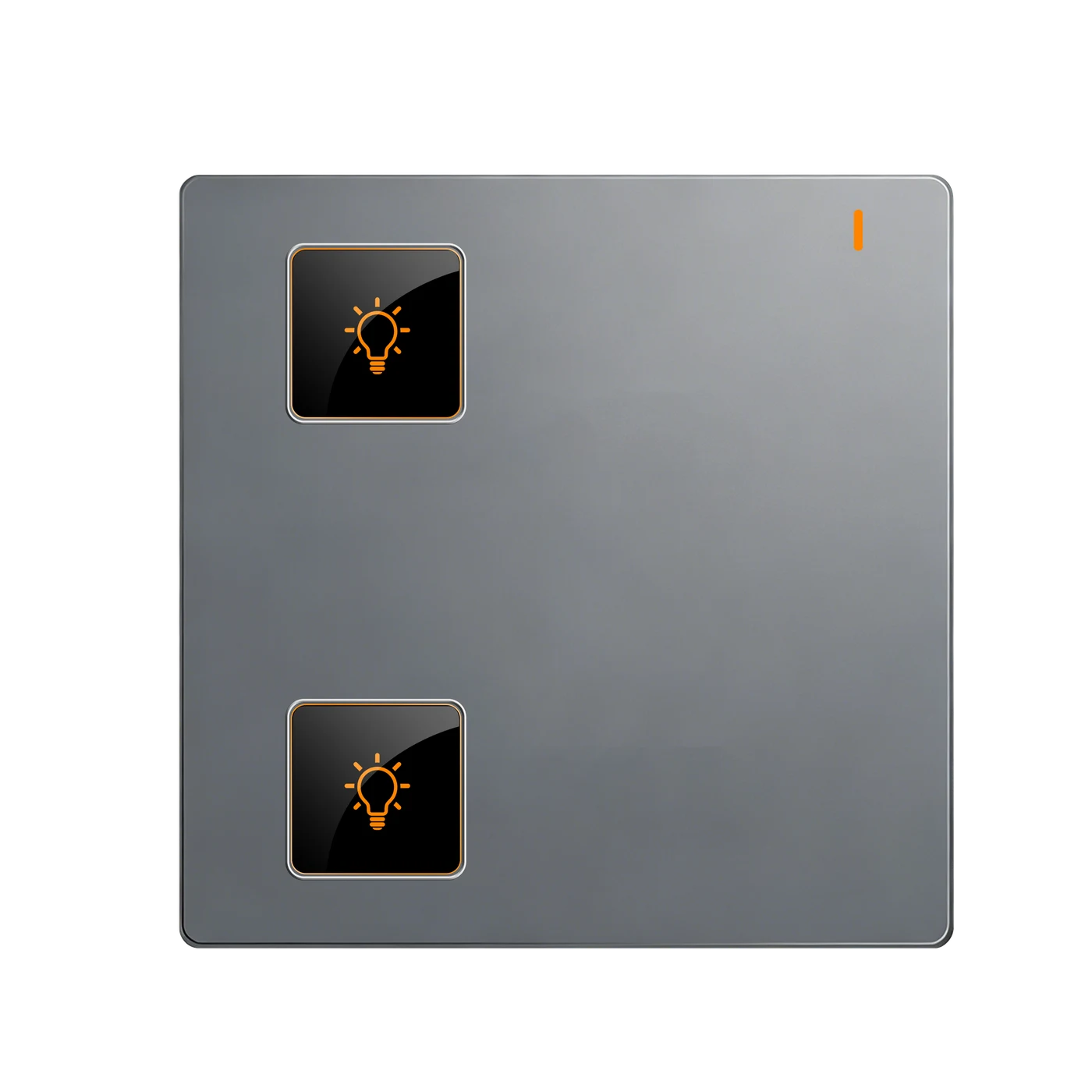
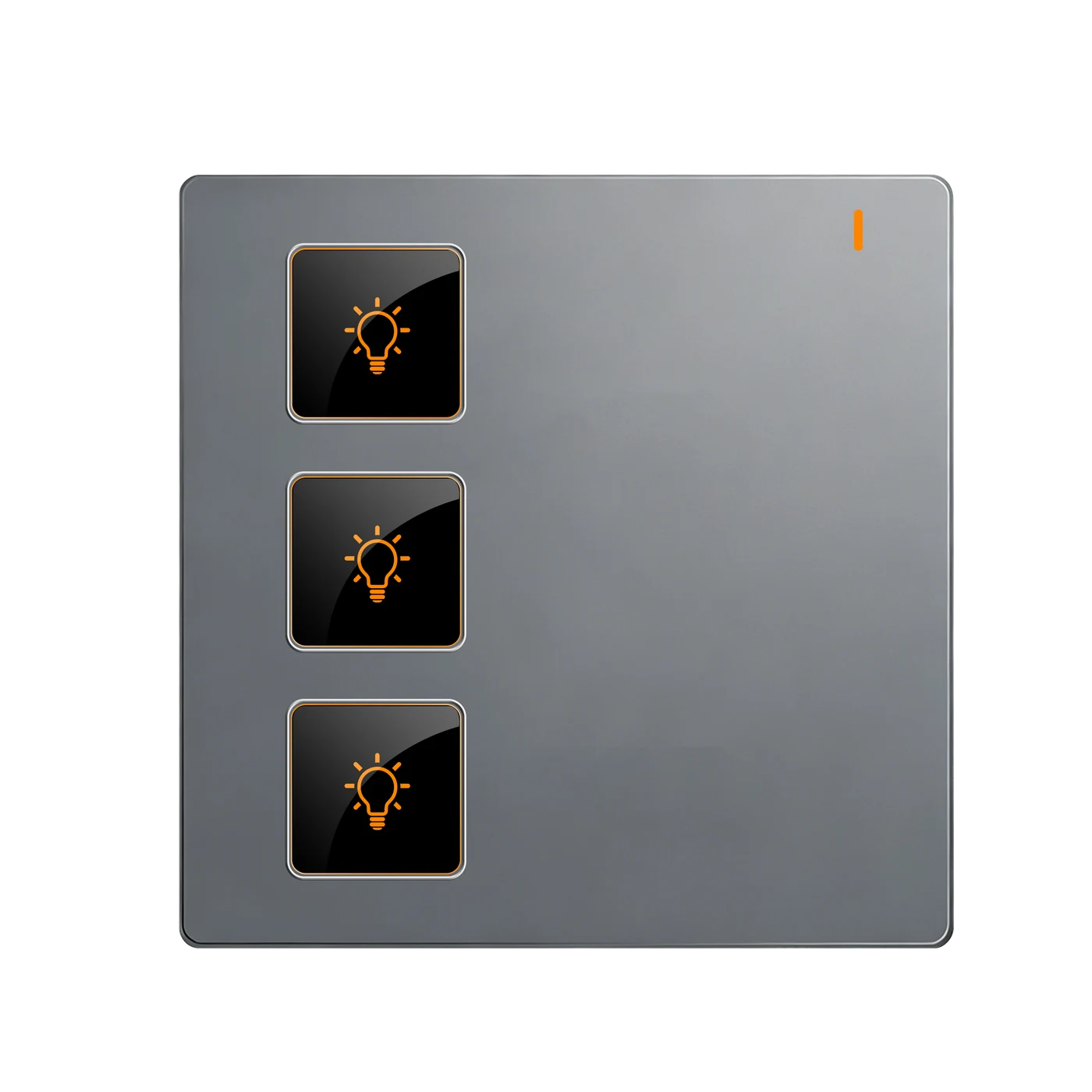
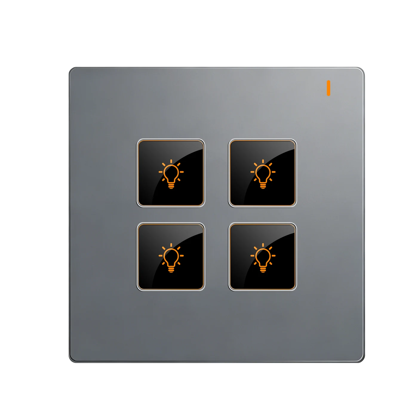
Selected: L10U-HS1-T. Each button operates a separate lighting circuit within 200 W; not a software mode change.
APPEARANCE, IN THE DETAILS
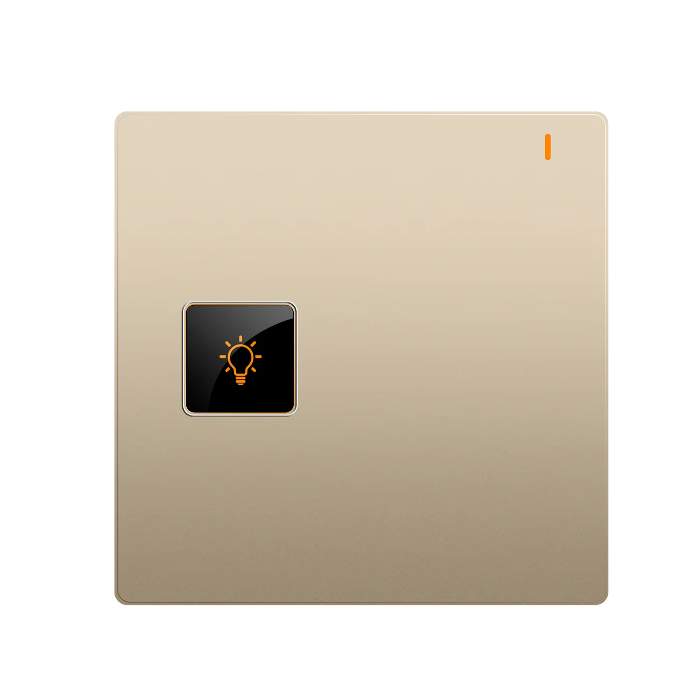
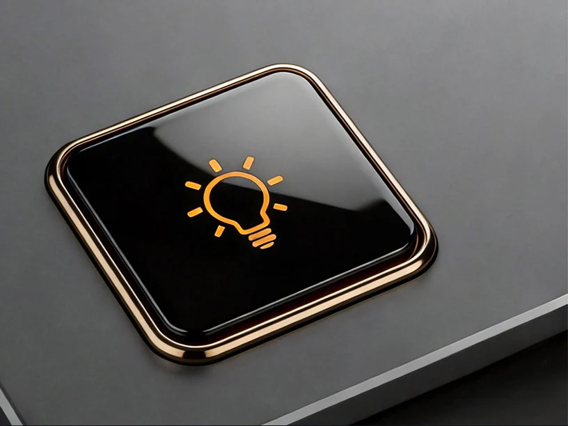
The black button surface contrasts with the surrounding panel. Its raised physical outline gives the design a clear focal point. Illustration shows the detail, not the current circuit count.
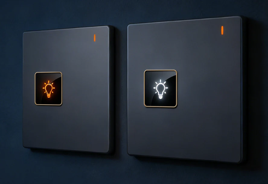
Choose the button backlight using the rear hardware selector with power isolated. The one-gang examples show the two backlight settings, not panel colours, RGB edge effects or app colour control.
PROJECT ARTWORK

Discuss the artwork and supply terms for project button markings. Text customisation is not supported. These are fixed physical markings, not editable screen icons; a pictogram does not add dimming, fan control or another electrical function.
Discuss button artwork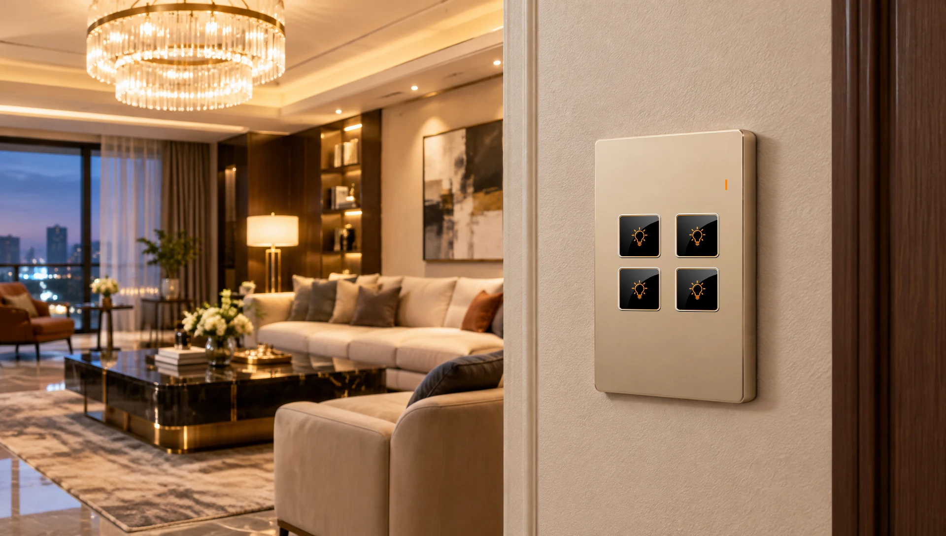
SMART LIVING
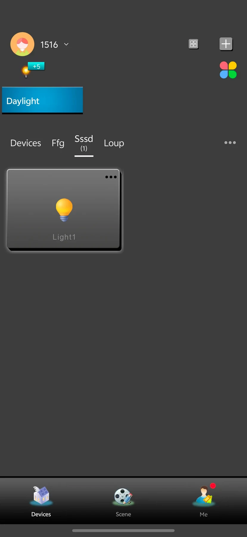
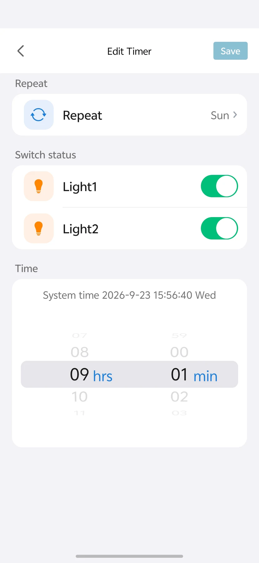
The supplied Smart Living circuit screen follows the selected physical gang count. The schedule screen is a two-circuit example, not a live connection. Remote use requires setup, internet and available services.
LANBON · L10U · WI-FI MESH
Compatible L10U series switches share a network without a dedicated gateway. Configure the first switch near the router as the master, then configure the remaining switches.
Control through LANBON Smart Living. Remote features still require a router, internet and available services. Switch Mesh does not extend Wi-Fi for phones or computers.
YOUR SELECTED HARDWARE
MODEL & INSTALLATION
L10U-HS1-T · EU · Tech Grey · 1-gang
All four physical circuit counts and both finishes share the shown dimensions for this format. Body depth is not a minimum usable box-depth guarantee. Ask support for current terminal instructions and the model-specific certification scope.
Compatible LED, CFL, incandescent and fluorescent lighting within the stated limits. Not for dimming, water pumps, unsuitable high-power inductive loads or overloaded circuits. Separate outputs must never be shorted or paralleled. Verify actual driver and inrush characteristics before specifying.
BUTTON & APP EXAMPLES
Supplied room illustration, not the currently selected hardware or a measured switching-response test.
Supplied LANBON app recording, not Smart Life or the currently selected physical circuit count.
PROJECT DOCUMENTATION
Contact support for current model-specific wiring and operating instructions, power-restoration behaviour, certification scope and project artwork/supply terms.
Project & channel enquiries