Power & wiring
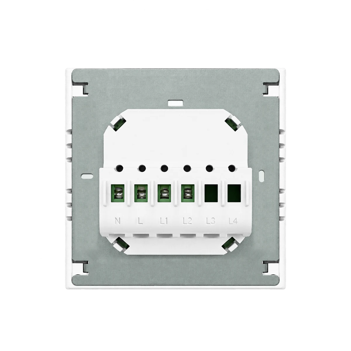
AC 100–250V · 50/60Hz · Live and neutral required

L8-HS / L8-HSU · 7-IN-1 LCD SMART SWITCH
LANBON versionChoose 1–3 lighting circuits, curtain control, scenes or a lighting-and-scene combination. Set one mode for the room, then control it from the screen or the app for your selected version.
LANBON version · EU / US · White / Black · Neutral requiredEVERYDAY WALL CONTROL
BEFORE YOU CHOOSE
Check the selected format, neutral wire, connected load and installation space with a qualified electrician.
AC 100–250V · 50/60Hz · Live and neutral required
On/off only. Up to 200 W per circuit; plain 1/2/3-gang modes: 200/400/600 W total.
Compatible AC curtain motor ≤200 W. Confirm scene wiring and combined-mode limits separately.
2.4 GHz Wi-Fi; app features require setup and available network services.
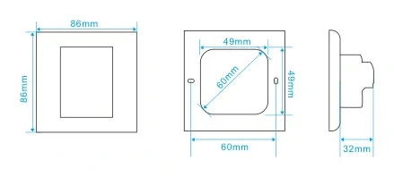
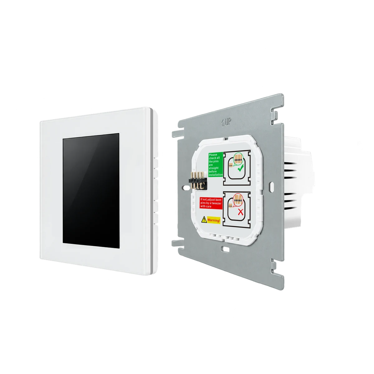
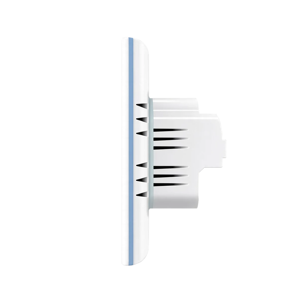
Depth >38 mm, with wiring space. EU fixing 60 mm; US fixing 83 mm. Follow the selected drawing.
SEVEN SELECTABLE MODES
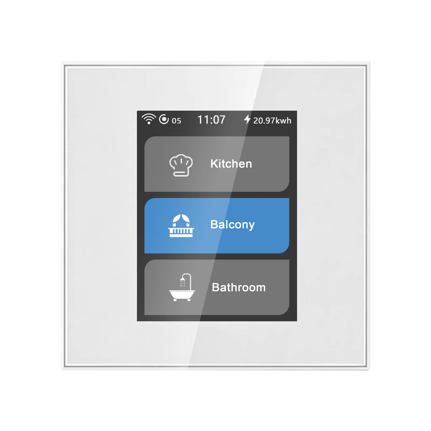
Choose one operating mode at a time. Plain lighting modes switch circuits; scene buttons trigger scenes configured in the app.
Switch one lighting circuit, up to 200 W.
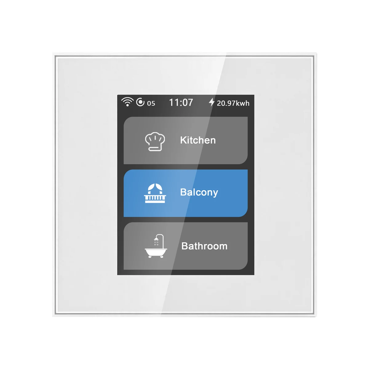
Select a tab to see the corresponding real device interface. Configure the actual operating mode on the device; this page is a preview.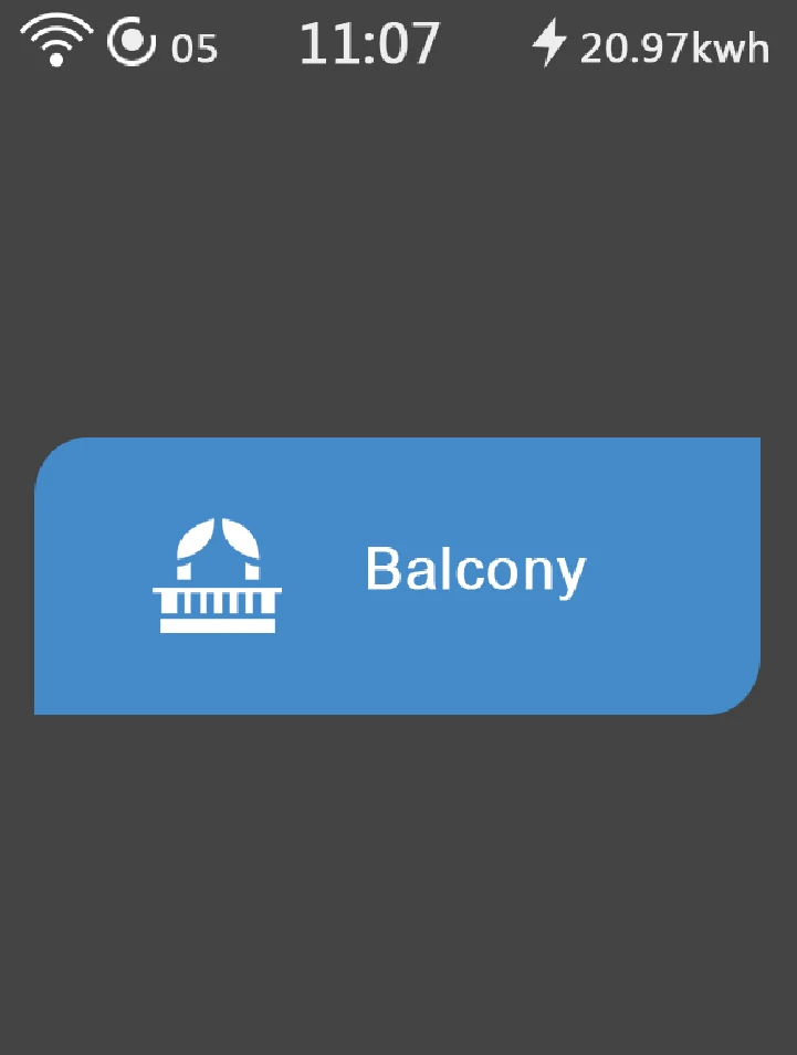
PERSONALISE YOUR PANEL
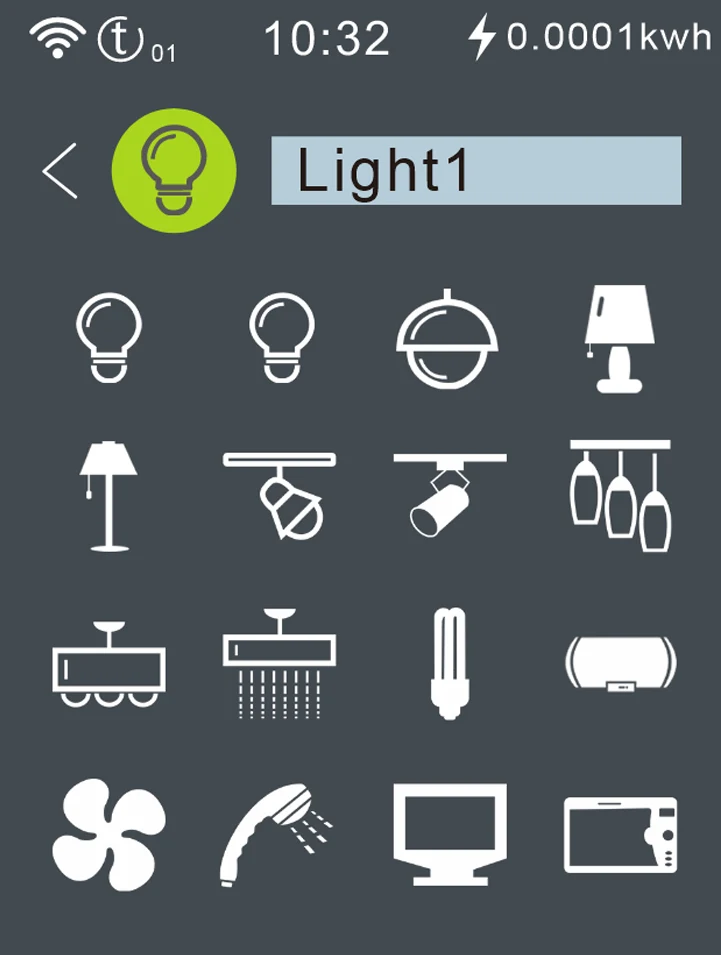
Set icons, names and display style on your L8 panel. Choose the display orientation to match the installation.
L8 · Icons
Choose an icon on the device to identify the light or control at a glance.
L8 · EDGE LIGHTING
Let the panel edge breathe and change colour while idle, or choose a colour of your own. The decorative edge light is separate from the controlled lights or appliance.
EXPLORE THE GLOW
Let the edge light fade gently in and out as its colour changes. Automatic mode takes care of the colours for you.
Set the edge light and its time settings on the device. These controls preview the effect on this page; they do not configure a switch.
DISPLAY & DESIGN
Adjust display brightness in the device settings. A tempered-glass panel and flame-retardant PC housing complete the wall-mounted design.
SMART LIVING
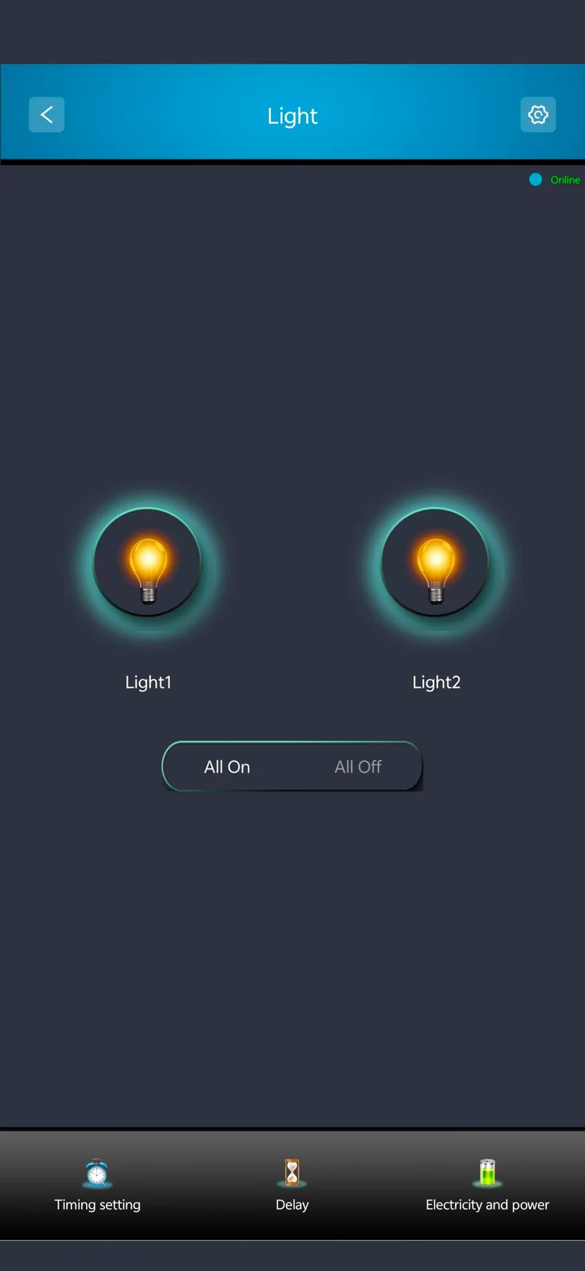
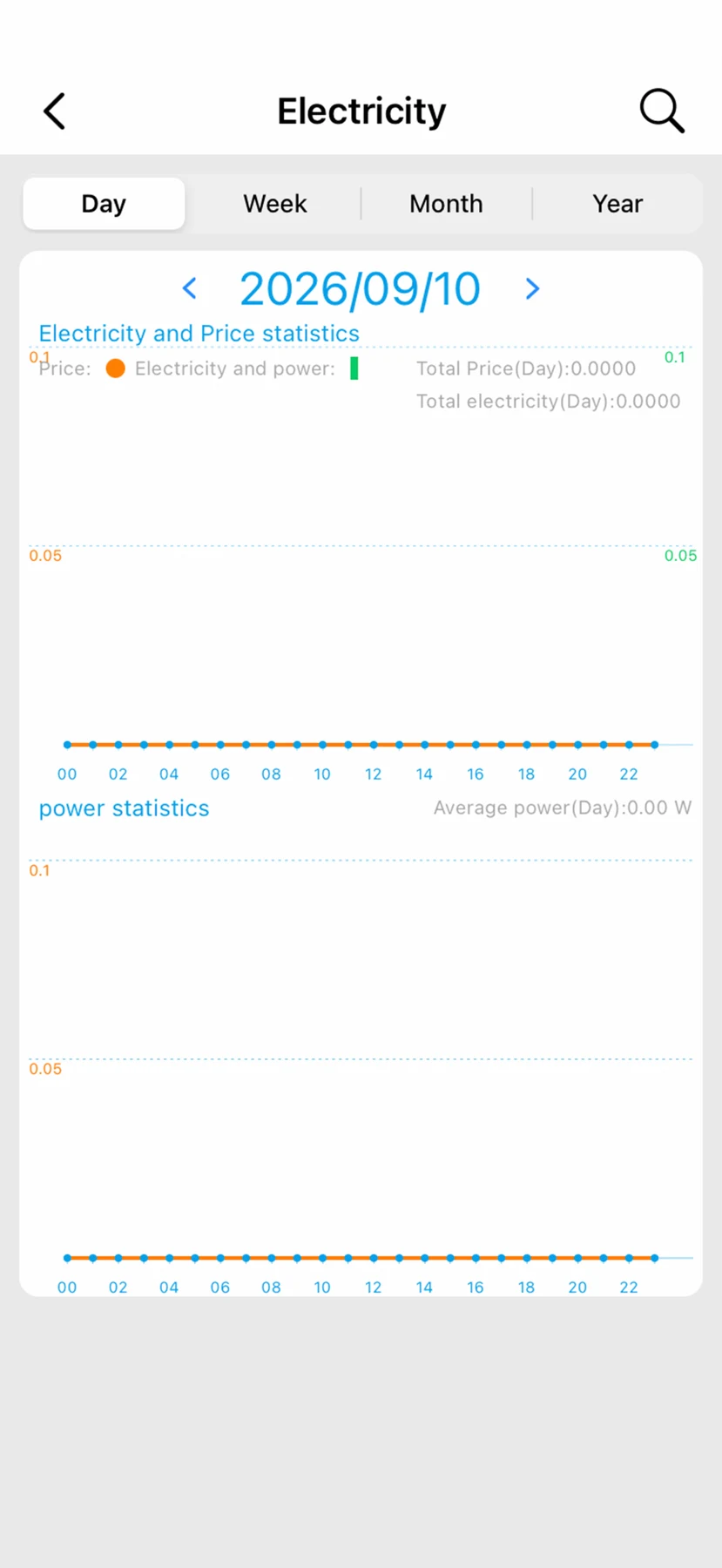
Use Smart Living for supported device control, schedules and energy information. Set up the device on 2.4 GHz Wi-Fi; connected features depend on network and service availability. Values in screenshots illustrate the interface.
WI-FI MESH
Mix compatible L8 switches in one network: 7-in-1, 4-in-1, dimmer, fan and water heater controls. Switches connect through neighbouring nodes, so each switch does not need a direct Wi-Fi connection to the router.
First configured switch7-in-1 switch · Master example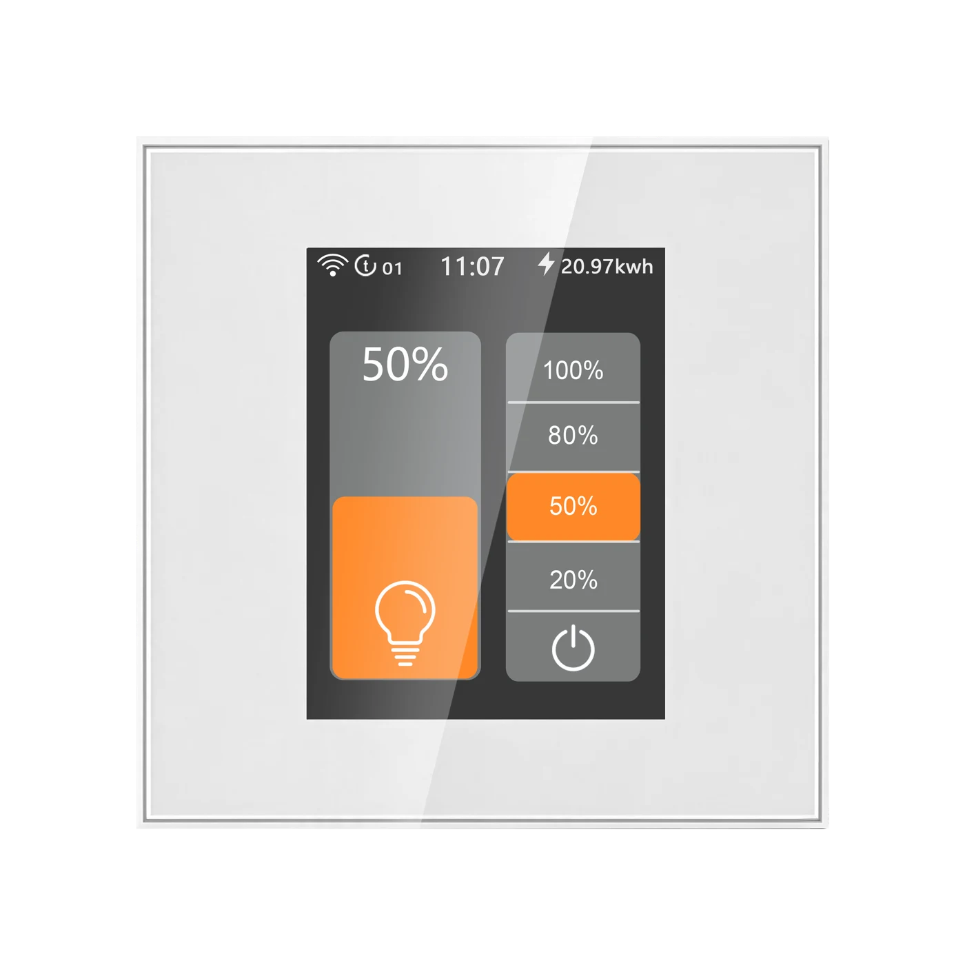 Dimmer switchConnects through Mesh
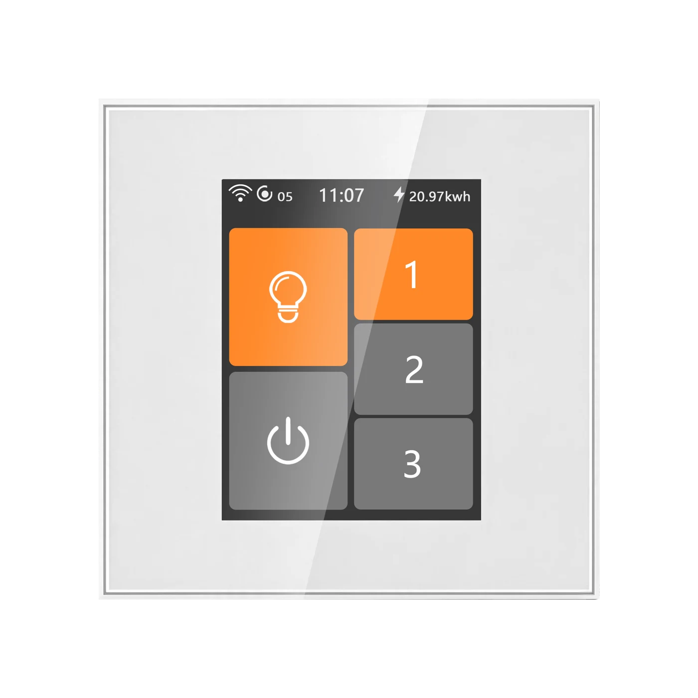 Fan switchConnects through Mesh
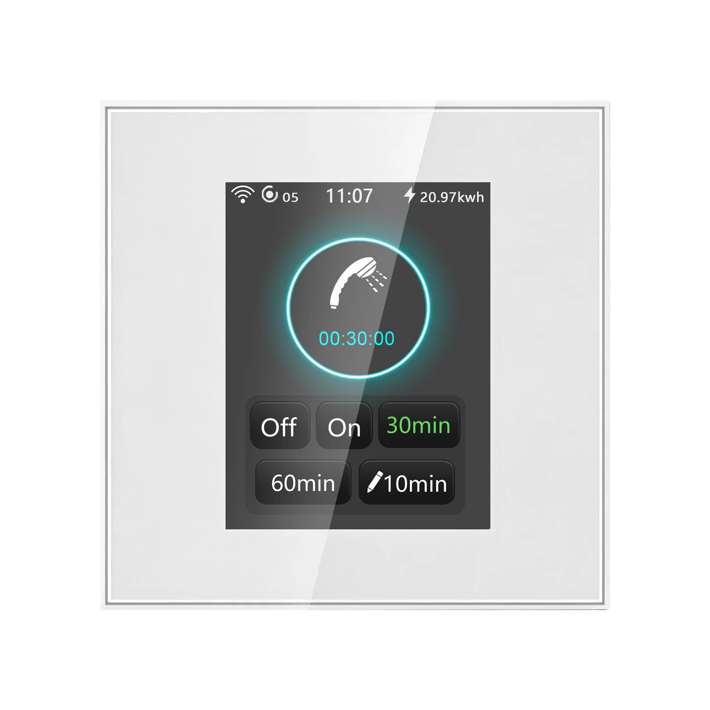 Water heater switchConnects through Mesh
Configure the first switch where the router signal is good. The system automatically sets this first configured switch as the master.
Complete setup for the other compatible switches. Keep adjacent Mesh switch nodes no more than 8 metres apart.
The switches automatically form their Mesh network. Any compatible switch can serve as the master when configured first; a separate gateway or host is not required.
L8 switches form a network within the L8 series; it does not extend household Wi-Fi for phones or computers. Remote app and cloud features still require the router, internet access and available services.
L8-HS · LANBON edition
Add compatible switch entities to Home Assistant using MQTT Discovery.
Connect Home Assistant →Send commands and receive device state through your own MQTT broker.
MQTT developer guide →Read device capabilities, send commands and retrieve state through the LANBON local API.
Use the local API →PRODUCT VIEWS
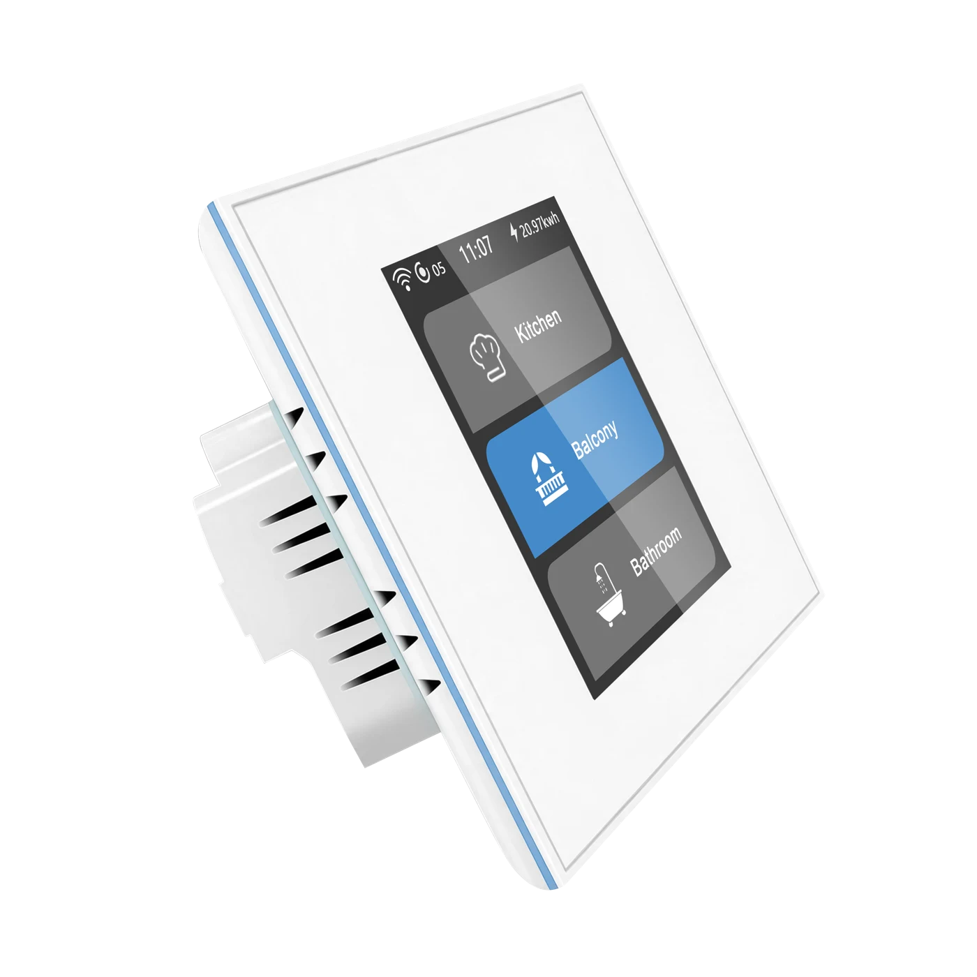
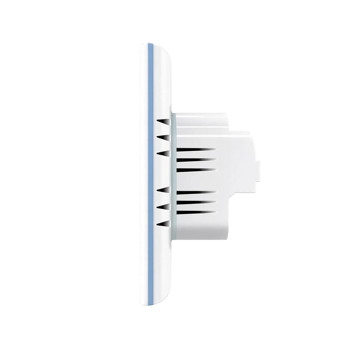
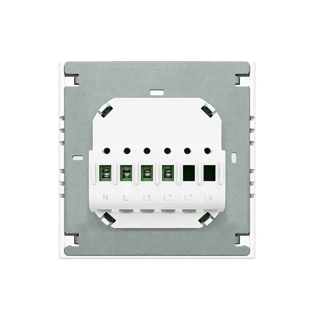
L8-HS · 86 × 86 mm · White
MODEL & SPECIFICATIONS
Dimensions, fixing points and files follow the selected EU or US panel.
EU: 86 × 86 mm square or ≥60 mm round box; 60 mm fixing centres.
Keep power isolated during installation. Verify the actual terminals, load and current wiring instructions before connection.
LOAD COMPATIBILITY
LED, CFL, incandescent and fluorescent lighting, with compatible mains, constant-current or constant-voltage LED drivers. No minimum load is specified.
Compatible AC curtain or tubular motor ≤200 W. Interlocked relay outputs must not operate simultaneously.
Dimming applications, DC curtain motors, high-power heaters, pumps or other high-power inductive loads. Never short or parallel outputs.
INSTALLATION
WATCH IT WORK
Mode selection and operation on the L8-HS display.
Remote controls shown in the supplied Smart Living demonstration.
DOCUMENTS & SUPPORT
Open a document preview, read the full PDF or download it. For current operating and wiring instructions, contact technical support.
The compliance attestation lists its own scope and conditions; it is not a blanket approval for every market or application.
Get product support